
Installation Guide for SafetyCam Plus & SafetyCam Pro for OEM


Installation Overview:
- Connect and Test SafetyCam: Connect the SafetyCam and perform a test to verify its functionality.
- Associate SafetyCam with Vehicle: Ensure the SafetyCam is linked to a vehicle in the Azuga Fleet Mobile app or Web platform.
- Adjust Viewing Angles: Utilize the Live Streaming feature to set optimal viewing angles.
- Mount your SafetyCam: Ensure the SafetyCam is mounted securely to prevent any movement.
- Confirm Successful Installation: Press the emergency button to trigger a “Button Pressed” event and confirm proper camera installation.
Installation Steps:
Step 1: Connect and Test Your SafetyCam:
Connect your SafetyCam (Plus or Pro) using the provided hardwire kit. Hardwiring draws power directly from the vehicle’s fuse box, allowing the camera to operate even when the engine is off.
This ensures:
- Automatic startup when the vehicle is turned on
- Standby (parking) recording while parked
The vehicle must supply 12V or 24V with a minimum 2A current.
For full functionality, connect the camera to a fuse with constant power. This ensures the camera remains operational while parked and starts recording automatically when the vehicle is turned on, and it communicates seamlessly with the fleet tracking system.
A. Prepare for Connection:
- Ensure your vehicle is turned off.
- Choose an area with good network connectivity.
- Since this process involves working with the vehicle’s electrical system, seek professional assistance if you are unsure or inexperienced.

|
Note: When the vehicle is off, the SafetyCam still draws a small amount of current (~32 mA) to remain in standby mode and retrieve recordings. |
B. Gather Components:
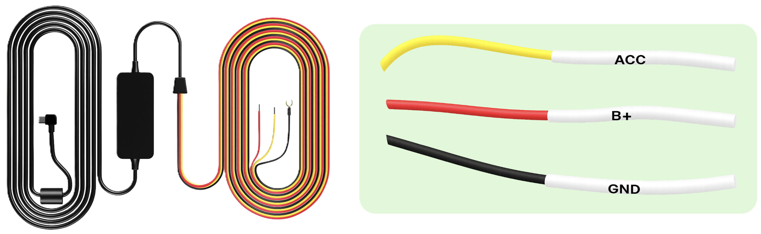
Before starting the installation, collect the necessary tools and components. The hardwire kit is designed for ease of use, with clearly labeled wires to simplify setup.
B (1). Required Components:
- Hardwiring kit, including: Add-a-Fuse kit and fuse tap.
- SafetyCam power cable with a connector on one end (to plug into the SafetyCam)
- Three hardwiring leads extending from the opposite end of the power cable:
- Red (constant power)
- Yellow (ignition/ACC)
- Black (ground)

B (2). Wire Functions and Labels:
-
Red (Constant Power) – 12V
- Labeled as “B+” on the wire.
- Connects to a constant 12V power source that remains active even when the vehicle is turned off. This enables continuous camera operation.
- Yellow (Ignition Power) – 12V / 0V
- Labeled as “ACC” on the wire.
- Connects to a switched power source that provides 12V when the ignition is ON and 0V when OFF. Triggers the camera to power on only when the engine is running.
- Black (Ground) – 0V
- Labeled as “GND” on the wire.
- Connects to a grounded metal bolt on the vehicle’s chassis. This completes the electrical circuit and ensures stable operation.
C. Locate and Access the Fuse Box:
- Check your vehicle’s owner manual to find where the fuse box is.
- It might be under the dashboard, near the glove box, or elsewhere depending on the car model.
- Open the plastic panel to access the fuse box. You might need to use a small trim tool or just pull a tab.
D. Identify Constant and Ignition – Switched Fuses in the Fuse Box:
D (1). To identify a constant power fuse:
- Turn OFF the vehicle.
- Use a circuit tester or multimeter to locate a fuse that remains powered (shows 12V) even when the vehicle is OFF. This indicates a constant power fuse.
- Use this slot for the red (constant power) wire from the hardwire kit.
D (2). To identify an ignition-switched fuse:
- Turn the ignition ON.
- Use the circuit tester or multimeter again to locate a fuse that powers on (shows 12V) only when the ignition is turned ON and 0V when OFF. This indicates an ignition-switched fuse.
- Use this slot for the yellow (ignition power) wire from the hardwire kit.
E. Prepare Add-a-Fuse Kits:
Two Add-a-Fuse adapters are used:
- One for constant power (red wire)
- One for ignition-switched power (yellow wire)

E (1). For Constant Power (Red Wire)
- Take one Add-a-Fuse kit.
- Remove the original fuse from the constant power slot.
- Insert the original fuse tap into the second slot (marked as #2 in the picture) of the Add-a-Fuse kit. This preserves the original circuit.
- Insert the provided SafetyCam fuse tap into the first slot (marked as #1 in the picture) of the Add-a fuse kit. This creates a new protected circuit and powers the SafetyCam.
- Prepare to connect the wire from the Add-a-Fuse kit to the red wire from the hardwire kit.

E (2). For Ignition Power (Yellow Wire):
- Take the second Add-a-Fuse kit.
- Remove the original fuse from the ignition-switched slot.
- Insert the original fuse tap into the second slot (marked as #2 in the picture) of the Add-a-Fuse kit. This preserves the original circuit.
- Insert the provided SafetyCam fuse tap into the first slot (marked as #1 in the picture) of the Add-a Fuse kit. This creates a new protected circuit.
- Prepare to connect the wire from the Add-a-Fuse kit to the yellow wire from the hardwire kit.
|
Important: Ensure the fuses are inserted in the correct order and orientation:
Installing them in reverse may prevent the SafetyCam from receiving power.
|
F. Prepare the Constant Power (Red) and Ignition (Yellow) Wires:
- Expose the Wires:
- Strip a small section of the yellow (ACC) and red (B+) wires to expose the metal core.
- Insert the Wires Into the Terminal Crimp Connectors:
- Use the terminal crimp connectors provided with the Add-a-Fuse kit. One for each wire.
- Insert the exposed end of the red and yellow wires separately into the back of the connectors, ensuring they are fully inserted.
- Crimp the Connectors:
- Use a crimp tool or needle-nose pliers (for insulated terminals) to firmly crimp the middle section of each connector, securing the wire in place.
- Repeat this step for both red and yellow wires.
- Perform a Pull Test:
- Gently pull each wire to ensure it is securely crimped and does not come loose.
- Prepare for Add-a-Fuse Installation:
- Ensure the crimp is secure and the connector is tightly attached to the wire. The Add-a-Fuse adapters will be inserted into the identified fuse slots in the fuse box.

G. Install Add-a-Fuse Kits Into the Fuse Box:
-
Test Fuse Slot Contacts:
- Start with the vehicle ignition in the OFF position.
- Use a circuit tester or multimeter to check which side (top or bottom) of each fuse slot has power.
- At this stage, only the constant power fuses will show voltage.
- Ignition-switched (ACC) fuses will not show voltage when the ignition is OFF.
- Now, repeat the test after switching the ignition to ON, and use a circuit tester or multimeter to check which side (top or bottom) of the ignition-switch fuse slot has power.
- Constant power fuses → continue to show voltage in both OFF and ON positions.
- Ignition-switched (ACC) fuses → show voltage only when the ignition is in ON.
- Insert the Add-a-Fuse Kits:
- Switch the vehicle OFF again.
- Insert the red wire’s Add-a-Fuse kit into the constant power slot.
- Insert the yellow wire’s Add-a-Fuse kit into the ignition-switched power slot.
|
Improtant:
|
|
Tip: Fuse orientation can vary between vehicles, so it’s always best to test before final installation. |
H. Make the Ground Connection:
The black ground wire usually comes with a ring or C-shaped terminal. Securely attach it to a metal part of your vehicle’s chassis to ensure proper grounding.
- Locate a nearby metal bolt on the vehicle’s body or chassis.
- Loosen the bolt slightly. Do not remove it completely.
- Slide the ring terminal of the ground wire beneath the bolt.
- Tighten the bolt securely to ensure a solid ground connection.

|
Tip: A loose ground can cause power issues. Make sure the bolt is firmly tightened. |
I. Power and Test:
- Plug the connector into the SafetyCam.
- Start the vehicle to test the SafetyCam. It should power on automatically.

I (1). Critical Setup Instructions:
- Power on the device and wait for 1 minute. During this time, you will hear OTA update audio notifications a couple of times.
- Afterward, unplug the device and plug it back in. The SafetyCam will be ready, and you can proceed with mounting it.
|
Note:
|
I (2). Check LED Indicators:
-
Blue Light:
- Flashes every 15 seconds – Normal connection.
- Stays constant – Abnormal connection.
- Red Light:
- Flashes every 15 seconds – No SD card detected.
- Stays constant – Emergency button pressed/Event recording.

J. Tuck Away the Cables:
Once the camera powers on successfully:
- Neatly run the cable along the vehicle’s headliner (interior ceiling).
- Route the cable from the A-Pillar down to the fuse box.

|
Important: Do not mount the SafetyCam until you have adjusted both the road-facing and driver-facing viewing angles. |
Step 2: Associate Your SafetyCam with the Vehicle:
- SafetyCams must be associated with a vehicle to function correctly, as well as create and store data for use on the fleet tracking web and mobile app.
- Correctly associating your vehicle will enable optimal performance of critical features like Live Streaming.
- This step will require administrative access to the fleet tracking web and mobile app.
Steps to Associate:
A. Access the Platform: Begin by accessing the Azuga Fleet Mobile app (recommended) or the Web platform to initiate the setup.
B. Follow Instructions: Carefully follow the detailed instructions provided in the SafetyCam - Vehicle Association document.
C. Confirm Association: Ensure the SafetyCam is successfully linked to the vehicle before proceeding to the next steps.
|
Note:
|

Step 3: Adjust the SafetyCam Viewing Angles:
- The viewing angles of the SafetyCam can be adjusted in real time using the Live Streaming feature on the Azuga Fleet Mobile (AFM) app or the Fleet Web platform.
- This enables precise fine-tuning of the camera’s position to ensure optimal coverage. Adjustments are quick and easy, improving both visibility and monitoring.
- For a simpler and more flexible experience, we strongly recommend using the Azuga Fleet Mobile (AFM) app for this process.
A. Prerequisites:
- Ensure the vehicle is parked on level ground and in an area with good network connectivity.
- Verify that the SafetyCam is properly associated with the vehicle.
B. Optimal Positioning for Road-Facing and Driver-Facing Views:
- Both the road-facing and in-cab lenses can have their viewing angles adjusted for optimal alignment.
- Proper positioning is crucial to ensure clear visibility of the road and the driver, as well as accurate monitoring and reliable event triggering.
- To adjust the angle, start by loosening the SafetyCam locking screws. Ensure both the road-facing and in-cab views are aligned for optimal coverage.
- Once the desired angles are set, tighten the locking screws to securely fix the SafetyCam in place, ensuring stable positioning and reliable functionality.

B (1). Road–Facing View:
- The road-facing lens must be positioned to ensure that the entire road ahead is clearly visible within the frame, without obstruction from any part of the vehicle or SafetyCam setup.
- The SafetyCam must be directed at the road, not the sky, to ensure accurate footage capture.
- The red line shown in the images serves as a focus guide. The SafetyCam should be adjusted so that the road is properly aligned within this frame—neither too high nor too low.

| Warning: Improper alignment of the SafetyCam can prevent road-facing events from being triggered effectively. |
B (2). Driver - Facing Views:
- The in-cab lens should be adjusted to clearly capture at least half of the driver’s body, including the head and shoulders, within the frame.
- The road-facing view should always take precedence over the driver-facing view to prioritize road visibility and event detection accuracy. Adjust both lenses accordingly to maintain this balance.

| Warning: Improper alignment of the SafetyCam can prevent driver monitoring events from being triggered effectively. |
C. Steps to Adjust the Viewing Angles:
There are two ways to adjust the viewing angles:
- Via the Azuga Fleet Mobile App (recommended)
- Via the Azuga Fleet Web platform
C(1). Via Azuga Fleet Mobile (AFM) App (recommended):
- Log in to the Azuga Fleet Mobile (AFM) app and enter your credentials.
- From the Dashboard/app’s home screen, navigate to SafetyCam > Live Stream.

- Click the Select Vehicle button to display a list of vehicles along with their SafetyCam status:
- Online: The SafetyCam is online and ready for live streaming.
- Standby: The SafetyCam is in an area with good network connectivity but is currently in sleep mode.
- Offline: The SafetyCam is disconnected.
- No Status: The SafetyCam has not reported any data. This could be due to installation failure, poor network connectivity, power loss, or no prior connection history. To enable live streaming, the SafetyCam must be brought back online.
| Note: Vehicles with an Offline status cannot be live-streamed. Move the vehicle to an area with better network connectivity until the status changes to Online or Standby. |
- Select a vehicle with an Online or Standby status to start the Live Stream.

-
Use the Rear View and Driver Facing buttons to switch views and adjust the angles:
- For the Driver Facing view, ensure that at least half of the driver’s body is clearly visible.
- For the Rear view, ensure a clear view of the road and that the camera’s angle is parallel to the ground.
- If Auxiliary Cameras are connected, additional buttons such as Aux 1, Aux 2, etc., will appear. Click these buttons and adjust their views as needed.

C(2). Via Azuga Fleet Web:
- Log in to Azuga Fleet Web platform using your credentials.
- Click on the SafetyCam tab and navigate to Live Stream.

- Under the Select Vehicle section, use the search bar or scroll through the list to choose a vehicle with an Online or Standby status to begin Live Streaming.
Here what these status means:
- Online: The SafetyCam is online and ready for live streaming.
- Standby: The SafetyCam is in an area with good network connectivity but is currently in sleep mode.
- Offline: The SafetyCam is disconnected.
- No Status: The SafetyCam has not reported any data. This could be due to installation failure, poor network connectivity, power loss, or no prior connection history. To enable live streaming, the SafetyCam must be brought back online.
| Note: Vehicles with an Offline status cannot be live-streamed. Move the vehicle to an area with better network connectivity until the status changes to Online or Standby. |

- Use the view selection dropdown at the top-right corner of the screen. Select “Rear View” or “Driver View” from the menu to switch views and adjust the angles.
- For the Rear view, ensure a clear view of the road and that the SafetyCam’s angle is parallel to the ground.
- For the Driver view, ensure that at least half of the driver’s body is clearly visible.
- If auxiliary cameras are connected, “Aux Camera View” will appear in the dropdown menu. Select it to switch views and make adjustments as needed.

Step 4: Mount your SafetyCam:
Your SafetyCam is nearly ready to use!
This step is critical for securing the camera in its optimal position and ensuring proper cable connections to deliver reliable performance and clear video coverage.
A. Prepare the Mounting Area:
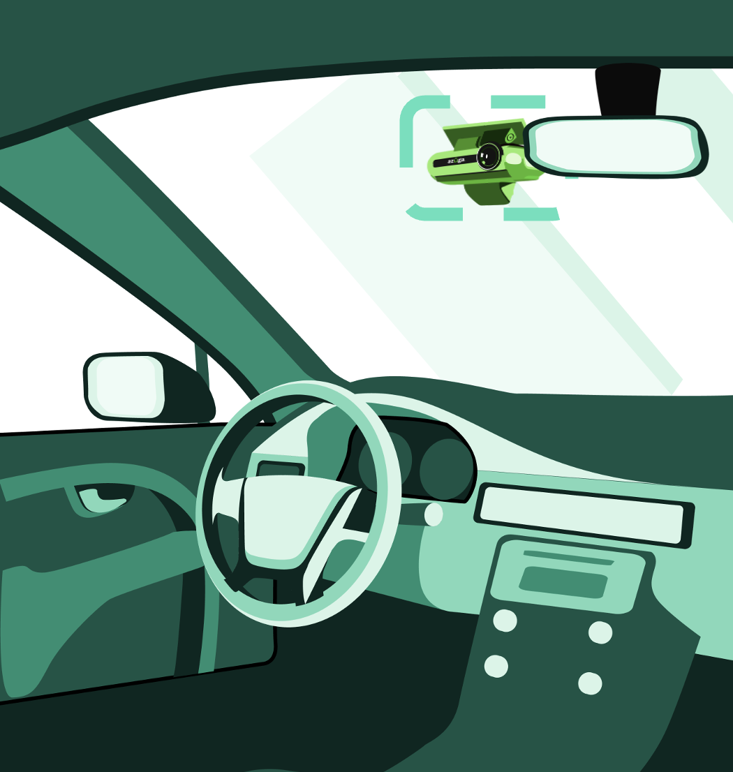
- Position the SafetyCam near the rear-view mirror, preferably on the driver’s side, to ensure optimal video quality.
- Verify that the location does not obstruct the driver’s field of vision or block the camera lenses.
-
Clean the windshield thoroughly with an alcohol wipe and allow it to dry completely for proper installation.

B. Attach the Mounting Plate:
- Separate the mounting plate from the SafetyCam.
- Peel the film off the back of the mounting plate and press the adhesive side onto the cleaned windshield to affix the plate securely.
- Press and hold the plate firmly for approximately 30 seconds to ensure it is mounted securely.
|
Tips for Secure Installation:
|
C. Attach the SafetyCam to the Plate:
- Attach the SafetyCam to the mounting plate by aligning the mounting holes on its back with the hooks on the rear plate.
- Slide the SafetyCam sideways until it clicks into place.

|
For SafetyCam Plus:
|

D. Complete the Connections:
- Connect the main connector to the SafetyCam.
- Attach the I/O port cover to the SafetyCam and tighten the screw with the hex key.
- Once all connections are securely in place, remove the protective film from the SafetyCam lens.


E. Cover the Exposed Cables:
- Cover the exposed cables coming out of the SafetyCam with the cable guide.
- Trim the rubber guide to the desired length with a pair of scissors.
- Peel the 3M tape from the back of the cable guide and adhere it to the windshield.

Step 5: Confirm Successful Installation:
- Press the emergency button on the camera after every installation. This action should trigger a "Button Pressed" event.
- This is a mandatory check to verify that the camera has been installed correctly and is functioning as expected.
- Within 10 minutes, the event video will be uploaded to the Azuga platform.
- This step is crucial to validate the main camera installation and ensure that events are being successfully uploaded to the system.
Auxiliary Camera(s) - Key Information:
- This is applicable to users installing our optional Auxiliary Cameras.
- These cameras are designed to enhance the functionality and coverage of your primary system, offering additional perspectives and improved monitoring capabilities.
PDF copy of the document: [Customer] SafetyCam Plus and SafetyCam Pro for OEM - Installation Guide
Last Verified on Sep 2025