
Installation Guide for Azuga ELD

Overview
We appreciate your interest in choosing Azuga as your ELD partner. This document provides instructions for a new user on
- How to install an Azuga ELD device into your vehicle.
- How to install ELD JBus into your vehicle.
Before installation, kindly note the device serial number (Printed on the device).
What’s in the box?
For OBD II Installation
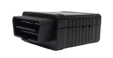
Azuga ELD Device |
|
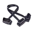
Extension cable |

|
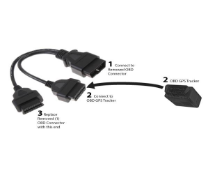
OBD Y-cable |
|

For Jbus Installation
JBus device |
Installation - Azuga ELD/OBD II
Based on the type of diagnostic port, the Azuga ELD/OBD II can be installed through any of the following:
1. Port Exposed.
2. Port Occupied.
Port Exposed:
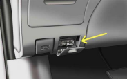
Locate the Vehicle’s diagnostic port. Typically, it can be found below the steering wheel. Follow the below steps to install Azuga ELD/OBD-II:

1. Switch off the vehicle or the unit on which the installation is performed.
2. Plug the Azuga ELD device into the diagnostic port if the port is exposed, as shown in Fig:1.
3. If the port is covered by a panel/door(Fig:2), use the extension cable to install the ELD/OBD device.
| Important: Ensure the OBD device is not protruding from the panel. |
4. Setup is initialized, and power is received once the LEDs on the Azuga device start flashing red five times. (Lights are located by looking into the micro USB port on the side of the Azuga ELD device).
5. Once the initialization is complete, the LED will turn Green, indicating that the device functions normally.
Port Occupied:
If another device already occupies the diagnostic port, install the Azuga device using the Y-cable.
1. Remove the other device from the diagnostic port.
2. Plug the female end of the Y-cable into the Port.
3. Connect the Azuga ELD/OBD device to one end of the Y cable.
4. Connect the removed device(Step-1) to the other end of the Y cable to complete the installation.
5. Setup is initialized, and power is received once the LEDs on the Azuga device start flashing red five times. (Lights are located by looking into the micro USB port on the side of the Azuga ELD device).
6. Once the initialization is complete, the LED will turn Green, indicating that the device functions normally.
Installation-Azuga ELD/JBus
Based on the type of port, a JBus device can be installed through any of the following:
1. 16 Pin Port
2. 6 Pin/9 Pin Port
16 Pin Port:
Locate the Vehicle’s diagnostic port; typically, it can be found below the steering wheel. Follow the below steps to install JBus
1. Switch off the vehicle or the unit on which the installation is performed.
2. Plug the Azuga device into the diagnostic Port (Fig:1).
3. If the port is covered by a panel/door(Fig:2), use the extension cable to install the device. Ensure the device is not protruding from the panel.
| Important: To get additional accessories like an extension cable, reach out to customercare@azuga.com |
4. Setup is initialized, and power is received once the LEDs on the Azuga device start flashing red five times. (The Lights are located by looking into the micro USB port on the side of the Azuga ELD device.)
5. Once the initialization is complete, the LED will turn Green, indicating that the device functions normally.
6/9 Pin Port
1. Plug the cable into the vehicle diagnostic port, as shown below.
2. Plug the device into the other end of the cable.
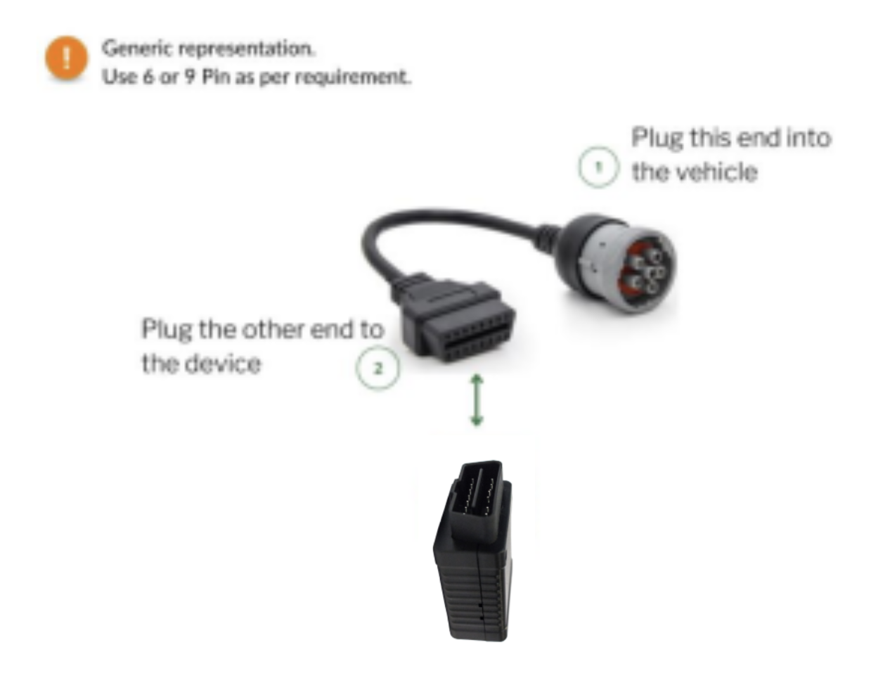
3. Setup is initialized, and power is received once the LEDs on the Azuga device start flashing red five times. (Lights are located by looking into the micro USB port on the side of the Azuga ELD device).
4. Once the initialization is complete, the LED will turn Green, indicating that the device functions normally.
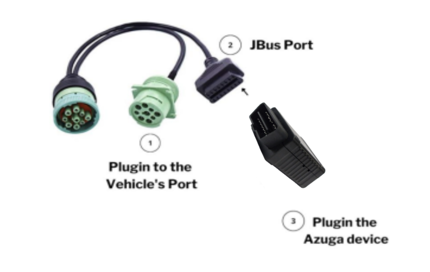
6/9 Pin Port- Occupied
If the vehicle diagnostic port is occupied already, install the Azuga device using the Y-cable.
1. Plug the female end of the Y-cable into the diagnostic Port.
2. Connect the Azuga ELD/OBD device to another end of the Y cable.
3. Setup is initialized, and power is received once the LEDs on the Azuga device start flashing red five times. (Lights are located by looking into the micro USB port on the side of the Azuga ELD device).
4. Once the initialization is complete, the LED will turn Green, indicating that the device functions normally.
PDF Copy: Azuga ELD - Installation Guide
Last Verified on March 2025